Last Modified:
The following descriptions and associated pictures are offered as observations on what we do to maintain and repair our ULT2001 embroidery and sewing machine. Copying what we do may void your warranty and you (not us) are responsible for problems which occur if you break your embroidery machine while trying to clean or repair it. If you're not mechanically inclined it may be wise to get help from a family member who is handy with small tools. Always unplug the machine prior to undertaking any work on it.
The methods and opinions below pertain to the Brother ULT and its twin, the Brother Galaxie. The Brother ULT2002D and ULT2003D are mechanically similar to the ULT2001. Since it is likely that the same engineers who designed these models also designed other Brother machines, some of the information below may apply to other models like the Brother Innovus and the Babylock Ellegante. However, since we have not worked with or on these machines we cannot say what might be helpful or harmful for these machines so it is up to the reader to determine whether anything found here applies to machines other than the ULT.
Some users of this site print the contents under the mistaken impression that the site might suddenly cease to exist and the information here become unavailable. We change the information here to cover additional areas occasionally so a printed copy may not contain the best information available -- check the site for the latest info. To allay fears of the site disappearing, there is a somewhat dated version at the Web Archive; go there and simply enter "annsultfixit.com" to access their copies of this site. It is also possible to store your own copy of the Fixit site on a CD or DVD (also preserving the hypertext links and pictures) much less expensively than printing; for example, see WinHTTrack for a free site copier or Google "offline browser" for similar programs. For those who need to print specific sections but want to eliminate the blue background: we suggest the Firefox browser where you can use the View/Page Style/No Style to change things easily.
My routine maintenance is mostly cleaning lint and threads from the places where they commonly collect. Each time I change the bobbin, I use the little brush to clean lint from the bobbin holder area -- the little plastic door is open and the bobbin is out so I take advantage of this.
Every third bobbin change I remove the needle plate and shuttle to clean the race and the bobbin sensor; while it is apart I check the needle plate and shuttle for burrs. In addition, I remove the light cover (pg 8- 1) to clean lint and threads from this area too. The bobbin arm and tension mechanism are also part of my cleaning routine. It cannot be over emphasized: CLEANING IMPROVES ULT RELIABILITY !!!
Since I have become more thorough in cleaning my ULT the number of difficulties (broken needles, tension problems, nesting, etc.) experienced has declined dramatically. The ULT seems to be more sensitive to lint and threads than other machines I've owned but if kept scrupulously clean, it works beautifully.
The Brother recommended routine maintenance is minimal (inadequate in my opinion); my experience suggests that a heavily used ULT is likely to require dealer attention within a few months unless routine maintenance is expanded to include much more rigorous cleaning. On the bright side, I believe the ULT will remain trouble free for very long periods if it is simply kept clean and oiled occasionally.
Click image for larger view
The ULT2001 is generally a trouble free embroidery machine. The most serious problem I've encountered since purchasing my ULT in January 2002 is lockup (aka freezing, seizing) due to threads jamming the works. It may be possible to avoid or at least minimize the frequency of lockups by performing the routine maintenance suggested above.
The symptoms caused by stray threads binding the mechanism include: noisy operation, failure to complete stitching a pattern, failure to complete outlining (re-trying will sometimes finish), machine stops intermittently, and eventually it locks up solidly such that the hand wheel won't move. I'm sure other causes can be found for any or all of these symptoms so observing these doesn't necessarily mean binding is the cause, just that it would be reasonable to check for threads in the bronze bearing and the area near the bobbin.
Prior to removing the front of the case, the cover over the end of the bobbin arm must be removed. This requires removing one screw in the rear of this cover, sliding it away slightly, then placing a flat screwdriver in the opening near the bottom front of the mating slot and moving the handle of this screwdriver to the left which will lever the plastic snap open (requires very little pressure). Use the brush to gently clear away any pieces of thread found near the cutter or in the area underneath. The manual recommends cleaning dust and lint from the shuttle area as routine maintenance; removing this cover (plus the needle plate) and cleaning threads from this area would be a reasonable addition to your routine maintenance. See page 8-1 for information on removing the upper (light) cover and page 8-2 for more information on cleaning the shuttle holder.
Provide an area and/or containers so the small covers and their associated screws may be kept together to avoid confusion when re-assembling; using several containers, one for each cover may be helpful until you become familiar with the procedure. Remove the light cover (see pg 8-1)to gain access to the screws which retain the front cover. Also remove the tension mechanism cover and the small cover near the bobbin winder. While removing or replacing the front cover, place the lever which releases the bobbin winder in the forward position (it's obvious when you look at it: the front cover can't be removed if it's in the other position).
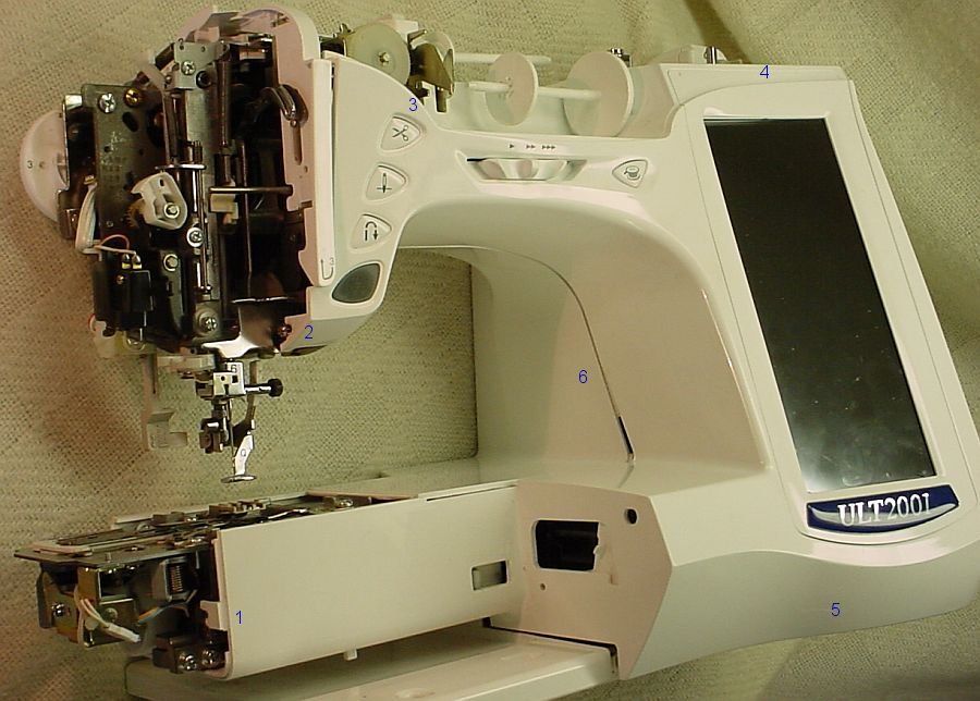
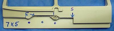
The first picture shows approximately where the four screws and two plastic snaps are which hold the front cover onto the ULT. The blue numbers (indicating the fasteners) are situated in a large approximate spiral beginning near the lower left and are best removed/opened in order from 1 to 6. The blue numbers show up well on a large CRT but are somewhat harder to see on a portable. (While the rear cover can be removed it doesn't improve access for cleaning so it is best left in place.)
The screws which retain the front cover are numbered 1-4 in the picture. Number 3 also holds the tension cover, number 4 is accessed from the back of the machine.
Lay the ULT on its back as shown (place a towel or blanket under it to protect the case) and release snap #5 near the rubber foot. We use a screwdriver to depress the tongue, then wedge something into the opening after releasing the snap so it doesn't re-click on its own. Press the case where the #6 is shown to release a similar hidden snap. There is another hidden plastic snap to the left of #5 which you'll need press upward to release after releasing #6.
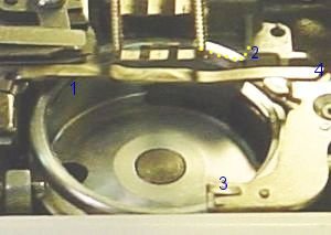
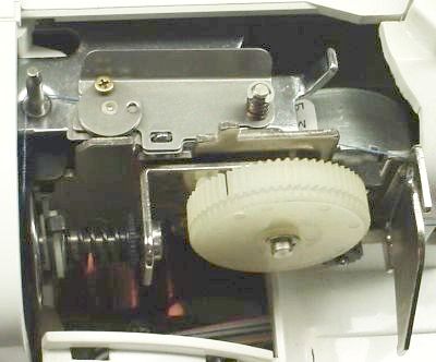
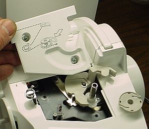
The second picture shows the ULT with the front cover removed.
The front of the case can now be carefully lifted from the machine; it remains attached to the machine by 3 flat cables -- take care not to place any strain on these cables while the front is separated from the machine. We leave the machine on its back and put the edge of the front under it to hold it in position (as in the picture) while removing threads and dirt from the works.
A possible trouble area is under the bobbin holder. There is a black gear which runs vertically and threads can become jammed under the bottom edge of this gear. In addition, there is a white horizontal gear/cam (see picture 2) which drives and is behind the black gear -- threads jam in the area between the white gear and its support and are difficult to see and/or remove. Rotating the handwheel often helps to locate stray threads.
Use tweezers (several types and sizes will come in handy) as well as a long needle to pick at threads which are wound around the shafts. Q tips can be used to wipe excess oil and grease off the surroundings but use care not to get their cotton fibers stuck in the works and make things worse. When wound around a shaft, threads often pick up oil and dirt (which turns them black) and are hard to distinguish from adjacent parts other than by gently picking at the suspect area with a needle.
Short pieces of thread sometimes fall into the area below the bobbin (probably severed by the built in cutter) and wind themselves around the shafts. This increases the friction, causing the machine to become progressively noisier and eventually lock up solid -- the hand wheel can't be moved. This is much more common than an actual failure of a mechanical part such as a bearing or shaft.
Surprisingly, it is far easier to put the front cover back on than to remove it. Ensure the bobbin winder lever is forward and align the cover in position starting with the top. 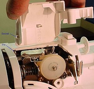 When the top is aligned, check the flat cables to ensure they're not going to be pinched, then work the left and right sides into place. The snaps which were so awkward to release will cause the case to click back together almost by itself. Check the arm area to ensure everything is snapped together properly, then replace the 4 screws which hold the front cover secure.
Replace the small covers and their securing screws, install the shuttle and needle plate and you should be all set. When replacing the cover on the tension mechanism it is possible to position it incorrectly: under the upper left corner is a socket in the plastic cover which MUST go over the small vertical metal pin on the machine -- if you miss with this it will intermittently have tension problems because the thread can be installed so it doesn't go through the tensioner properly (don't ask how long it took us to find that one).
Lockup, lock up, freeze, seize -- whatever you call it, the ULT will do it if you don't keep it clean. For those who haven't experienced a lockup, the main symptom is that the machine stops and won't restart. The handwheel won't turn as it normally does - using more than normal force to turn the handwheel can damage the mechanism so this isn't a good approach. I owned a Deco 600 prior to the ULT and it didn't require the careful cleaning that the ULT needs to avoid lock ups. I learned that the ULT requires cleaning the hard way: my machine locked up on two separate occasions almost a year apart; the dealer told me both times that it was due to threads in the works binding things up. While the repair cost was reasonable, it required two round trips (drop off and pick up) of an hour each way -- after the second lockup I started cleaning my ULT much more carefully! No lockups have occurred in over 8 years and I credit this to my careful cleaning and occasional oiling.
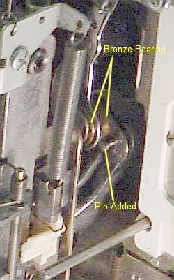 Based on input from readers of this site, by far the most common cause of lockups is thread caught near the bronze bearing visible on the crank arm when the light cover is removed. Brother uses bronze here because it is a critical bearing and they also fit it very precisely; it takes only a small amount of thread here to increase friction and lock things solid. Unfortunately, when thread makes its way into this bearing it may be impossible to see and very difficult to remove -- the needle bar assembly may need to be removed to access the trouble spot. In the picture you can see the small pin we added in the hole near the bronze bearing -- this helps to keep threads out of the bronze bearing and is easy to do. This pin must be short to avoid hitting nearby parts; a plastic or wood pin should be a press fit with a little Super Glue or Loctite for security. Thread can enter the bronze bearing on the left or right end; the pin protects only the right end so it isn't a complete cure for this common problem but it is a big help.
About half of site visitors who diagnosed thread in the bronze bearing were able to fix it themselves. Best guess is that this one isn't a cleaning issue. Operating the machine with the light cover removed allows observation of this area - the thread goes in a random direction as the chrome arm (at the top of the picture) descends and occasionally it happens to get wound into the bronze bearing.
I almost had this problem: the upper thread broke and when I tried, it wouldn't pull out easily. So I removed the light cover and found the end of the thread wrapped into the bronze bearing. I cut it off and then carefully unwound it out of the bearing with tweezers; it couldn't be simply pulled out. My guess is that some users don't open the machine when this happens, they just pull on the thread until it breaks off inside and then re-thread, leaving the broken piece of thread in the bearing. The thread eventually wraps itself completely into the bearing, locking the machine up solid. I can't be certain that this happens but it seems like a good hypothesis. The point here is: investigate carefully if the upper thread breaks inside where you can't see the cause.
Some users recover from a frozen machine by oiling. This may reduce friction enough in some cases to allow the machine to run but the friction will likely be higher than normal due to the thread lodged in the works. Another freeze may occur in a fairly short time, leading to more oil which may or may not do the trick the second time, etc. In general, oiling is helpful but doesn't get to the root cause of a frozen ULT.
Threads can get into the handwheel end of the machine too. Small pieces of thread here won't generally cause a problem if they wind on the shaft because the handwheel/shaft/white part inside the case rotate together so binding won't occur from this. 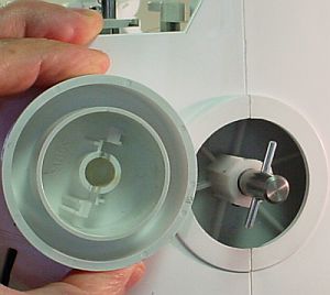 However, it is possible for thread from a cone to get wound onto the shaft and with a near-infinite source of thread the buildup can get large enough to cause problems.
The handwheel can be removed by pulling but it takes faith and quite a pull -- the handwheel flew across the room the first time we had the courage to apply enough force. The center section has a slot to transfer torque from the handwheel to the pin and a couple of fingers which snap over the pin in the shaft to retain the handwheel - we reduced the height of the raised part on the fingers to make it easier to remove in the future.
If you find a large buildup of thread on the shaft and/or suspect that thread may have gotten into the works below or beyond the handwheel then you might consider removing the front of the case as described above for better access.
Burrs on the stitch plate and bobbin holder (shuttle) were a common problem encountered with my ULT (until I began cleaning the ULT rigorously). The cause is a needle striking the stitch plate and/or the shuttle; the needle usually breaks as part of the event, often precipitated by nesting, a snag in thread coming off the cone, overly heavy stitching in an area, simple needle fatigue or excessive speed (I turned the speed down to 600 from 800 which reduced the frequency of the needle loosening and falling out). To minimize the occurrence of fatigue, I change the needle after approximately 4 hours (YMMV); I tighten the needle frequently, especially if the pattern calls for a lot of heavy stitching, and I use a screwdriver to tighten the needle (per the user manual, don't rely on your fingers). If a needle falls out while stitching, I discard that needle (it is likely damaged and will fail shortly). I haven't found a difference between the various brands of embroidery needles -- they all work well in my ULT.
Here is a picture of the critical area of a new stitch plate. Compare this to my 2 year old stitch plate which has had a number of burrs removed and just plain has a lot of miles on it. Clearly, the needle has come down completely out of the normal passage on a number of occasions plus you can see some small grooves on the area of the passage where most of the burrs have occurred. A 10x magnifier is helpful when looking for burrs, a "triplet" type or a "Coddington" will work well.
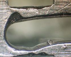 A burr on the stitch plate can cause a bewildering array of symptoms including tension, thread breaking, stopping, poor stitching, poor outlining, nesting, etc. When a needle breaks I always examine the stitch plate with a magnifying glass to see if a burr resulted; most burrs are on the side toward the operator but occasionally one is seen on the away side. The picture is a closeup of a typical burr with two needle strikes visible at lower right.
To repair a burr on the stitch plate, it is filed and smoothed with a needle file, then polished with a small strip of crocus cloth (fine emery cloth or 600 to 1500 grit carbide paper would work too). A 1/4 inch wide strip of crocus/emery/carbide is put through the opening in the plate and pulled back and forth to polish the surface after filing. Our repair technique is a two step process because crocus cloth is too fine to remove a large burr while filing alone leaves a slightly rough surface. A possibility we haven't tried is a fine diamond file as used for finger nails -- this may allow a single step repair. Needle file sets are available at hobby shops, hardware stores, Radio Shack or on eBay (of course); an inexpensive needle file set costs under $5 and will work fine for this application. Crocus cloth is available at hardware stores or auto parts stores. Hobby shops have fine carbide paper. If cost is not a consideration, there are even diamond needle file sets :-)
A burr on the shuttle is much less common but no less troublesome. Inspect the shuttle for burrs with a magnifying glass whenever it is removed. Remove it for inspection if problems occur with thread breaking, tension, etc. -the usual suspects- particularly after a needle breaks. To remove burrs from the shuttle the best tool we've found is an Xacto knife (from a hobby shop or hardware store) with a sharp blade. The shuttle is made of a soft plastic so the raised part of burrs can usually be sliced off cleanly; if a hole remains it shouldn't cause a problem but if it does then you'll have to remove a bit more with the knife. The key point is that the parts of the shuttle where the thread makes contact must be smooth or the thread will suffer and degrade the stitching. Our shuttle has a needle hole completely through it (it doesn't show in the picture but is between 1 and 2) which doesn't affect operation -- we removed the burr, of course.
Note: The ULT manual uses the term "race" (see pg 8-2 & 8-3) for the item we call "shuttle". The word shuttle originally designated the part used to hold the bobbin in a weaving machine. Sewing machines adopted the term to designate the part which holds their bobbin. A race is a groove in which an item or bearing slides. We suspect this is an error in translation and will use what we maintain is the correct term (I'm sure the translator's English is better than my Japanese but suspect my technical English is better than his :-) . If you look at an old Singer manual you'll see where we got our definition.
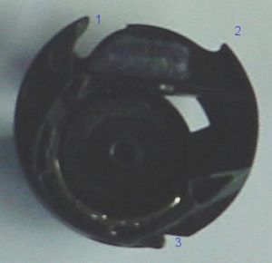
Inserting the shuttle into the race is a little trickier than the manual suggests (pg 8-3). Our pictures show numbers 1-3 and the corresponding points must be aligned properly (plus, you have to hold your tongue right) in order to insert the shuttle.
The race must be positioned correctly to allow the shuttle to be inserted. The picture below shows the proper setup. If you sight along a line between the points indicated by the two yellow dots and then rotate the handwheel to move the point on the race indicated by the green dot onto that sight line then you will be able to insert the shuttle. 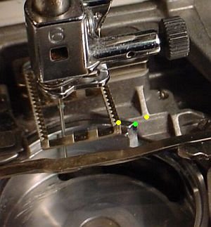 The line looks bent but, trust me, if you sight between the yellow points the other point can be rotated into line.
In the pictures above, the point on the shuttle numbered 1 must be above the race groove at point #1, point #2 on the shuttle must fit into the notch #2 on the race, and the notch in the shuttle #3 must simultaneously pass the shelf #3 near the race. The most common difficulty occurs when point #1 slips off the race groove, preventing the shuttle from fitting into place. To ease insertion, lift the end of the arm, #4 in the picture, slightly with your fingernail (less than 1/8 inch, don't force it or bend the arm) and insert the shuttle -- lifting #4 ever so slightly allows #1 to be kept above the race, allowing easy insertion. It may take a couple tries but have faith, with patience and a gentle touch it will drop in.
The arrow in the picture at right shows wear on the bump between the two screws on the shuttle, near point #3 from the earlier picture. The indent on the bump is wear from thread rubbing this area on each stitch- this bump should be smooth. After 6 years of heavy use my machine began nesting frequently, the top thread often broke (usually accompanied by a snapping sound) tension varied, and stitching was irregular; replacing the shuttle solved all these problems. If your machine exhibits any or all these symptoms it is simple to remove the shuttle and inspect this area. Check for and remove burrs on the shuttle while it is out since these can cause similar problems.
A quick (rough) check of the "timing" is possible while the shuttle is out. The needle should be at its lowest position when the point marked with a green dot above is directly below the right side of the feed dog. The timing can drift for various reasons - sewing heavy material or very thick designs, for example - where the symptoms can include nesting and other stitching problems. The drift is usually due to parts on internal shafts rotating slightly from their desired position; correction requires loosening the set (grub) screws, aligning timing marks, and retightening the set screws - not easily done by most owners.
The ULT tension mechanism is the best that I have ever used -- when I have a tension problem it is always a symptom of something going wrong. I have used upper thread from most major manufacturers and bobbin thread from several sources; I have never adjusted the bobbin tension and seldom need to change the upper tension.
I use thread directly from cones located on a stand to the left rear of the machine; the thread feeds around the chrome hook on the top of the machine (normally used for winding bobbins) and on into the machine. This generally works well but some cones occasionally generate little loops in the thread and these can lasso this hook, resulting in increased tension. It is hard to see this when using light colored thread so be forewarned. Of course, any other oddities in the way the thread is delivered to the machine can increase tension so this is an important thing to check.
A near-empty bobbin sometimes affects tension, causing white heads to appear -- apparently due to the bobbin jumping around in the shuttle. This is very quick and easy to check so it should be done before looking for other causes. Check the needle too -- while less likely as a source of tension problems, it is easy to check.
The next thing to do when tension problems occur is remove the stitch plate and clean the shuttle and race; check carefully for thread or lint in the tension mechanism on the shuttle. While the shuttle and stitch plate are out check for burrs, a common cause of tension problems. If you have broken a needle recently, tension problems may well be a result.
 Next, check the upper tension mechanism for stray threads or dirt and especially for proper installation of the tension cover -- improper installation can cause intermittent tension problems.
The rectangular plate ("tension plate" in the parts list) near the top of the picture is normally somewhat loose; when the foot is lowered, the round part at the left side of the tension plate drops a bit to snug it but ours remains somewhat loose. The Phillips screw in the round part is an adjustment; we don't fiddle with it :-) The large white gear is controlled by the tension setting available from the ULT's screen; it sets the upper tension via the spring and "thread tension washer" just visible at left. The thread tension washer is also released by raising the foot -- work the foot up and down while watching this area to see how it all works. With power off and the foot down you can rotate the white gear to see how it compresses the spring to set tension.
Remove the bobbin arm cover and check for threads and lint in the works. Remove the light cover and check for threads and lint there also.
The lower (bobbin) tension is set by a flat spring in the shuttle. The adjusting screw allows the spring pressure to be changed - as noted elsewhere, I never fool with this setting. Check carefully for lint, dirt, etc. between the flat springs and the thick metal guide - this is one place where it is reasonable to blow the dirt out. If your machine has been in use for a few years, check for shuttle wear.
The above checks have allowed me to resolve all of the tension problems which I have encountered with my ULT.
One detail: the upper tension adjustment (the knurled knob at the right end of the upper tension spring in the picture) is supposed to be secured with Loctite; mine wasn't so I put a dot of white paint on the knurl and I check it occasionally. So far, it hasn't moved but if it does I will add some paint on the threads to stabilize it. Again, don't fool with this adjustment -- clean the tension mechanisms (top and bottom) and use the tension adjustments provided via the LCD screen P.3
Proper tension causes the interlock between the top and bottom thread to hide itself in the cloth layer when sewing; for embroidery this interlock is generally lower, causing the color of the top thread to show on the back of the embroidery. Having the top thread show on the bottom of embroidery ensures that any minor changes in tension due to dense stitching don't cause the bottom thread to show on top. Each time it is turned on, my ULT sets the default upper tension to 4 for embroidering or to 5.2 for sewing -- the reduced upper tension for embroidery ensures that "white heads" won't show; increased upper tension while sewing hides the interlock between top and bottom threads within the cloth.
The upper and lower (bobbin) mechanical tension adjustments are made at the factory (or dealer) by using small spring scales; a designated pull is exerted on the thread and the adjustment is set so that the thread can just pass.
Thread tension is a balancing act, where upper tension must match bobbin (lower) tension to place the thread interlock below or within the cloth. If bobbin tension is increased (by turning the screw) then upper tension must be adjusted to compensate via the ULT's screen (the default tension will no longer be correct) to position the thread interlock as desired -- so, it may seem that tension doesn't matter as long as the balance is correct. However, increased top and bottom tension - even though properly balanced - can cause the cloth to pucker or the thread to break. Reduced tension can cause the machine to stop and/or loopy embroidery threads.
Brother has determined the tension settings which result in the best overall stitching performance in the ULT and accommodates special situations with tension adjustments accessible from the ULT's screen. This doesn't mean that bobbin tension should never be adjusted but it does mean that it shouldn't be done simply because the adjustment is easy to find and turn. If you decide you must adjust bobbin tension, be sure to use Loctite or nail polish to seal the adjustment screw in place else vibration may slowly change the adjustment...
There are 4 separate adjustments for tension:
The first two are mechanical settings which adjust the setup of the machine: the basic thread tension and the balance between upper and lower tension. The last two allow the tension setting to be fine tuned to accommodate any minor change which occurs due to wear, thread differences, or simply the way a design sews out. If you find that the top tension is always too tight then you can use screen P.3 to change the tension and your machine will retain this until you change it again. Or, if you find that a particular design needs the tension changed to sew out properly then use the bottom of the sewing screen; when you turn the machine off it will forget this change and work as it did previously when you next power up.
Some details on how all but the bobbin tension work. The white gear (visible when the tension cover is removed) rotates to change the tension applied to the upper thread. The knurled nut is set at the factory to balance the tension from the bobbin when the screen P.3 and the sewing screen are both set to 4 (the default for embroidering). When you change the screen P.3 tension, the gear will rotate to a different position because of the changed setting, thus changing the tension applied via the spring. Similarly, if the tension setting on the sewing screen is changed then the gear will rotate to another position, further changing the upper tension setting. The actual rotation of the gear (and the tension) is set by the sum of these two settings, i.e. the effect adds up. Note that the gear doesn't move when you change the setting, it waits until you begin to sew - add a colored dot on the gear to aid in keeping track of the rotation angle vs tension setting if you're curious. In normal use, the screen P.3 adjustment should allow sufficient range to solve most all tension drift problems -- tension errors so large they can't be handled are likely due to a problem from dirt or thread caught somewhere in the upper or lower tension mechanism.
Brother's description of the Embroidery Tension Setting on screen P.3 (added in 4.01) doesn't make clear that this adjustment is retained when power is removed. This setting allows the user to compensate for using a different type of thread or for minor drift in the balance between upper and lower tension. The ULT's computer retains this setting until the user changes it, unlike the tension setting at the bottom of the sewing screen (see manual, pg 5-19) which reverts back to the default on power up (this is used to temporarily change the tension as needed for some designs). Use of the new semi-permanent "Embroidery Tension Setting" allows accomplishing much of what formerly was done via the bobbin adjusting screw; however, it is easy to put it back as it was originally should you subsequently find the underlying cause for the tension shift and repair that (burr, dirt, etc.) -- backtracking is not so easy if the bobbin screw was turned.
The point of the "Embroidery Tension Adjustment" on screen P.3 is that if the tension setting of your machine shifts slightly for unknown reasons, and careful cleaning doesn't fix the problem, then you can adjust the tension in an easily controlled and easily reversible way. As long as you are happy with the way it stitches after this adjustment, no further mechanical adjustment or action is needed except it might be wise to seal the bobbin adjustment screw as mentioned previously.
Both mechanical tension adjustments are sealed at the factory with purple LocTite (thread locker); this keeps them from changing due to vibration and indicates to me that Brother believes they shouldn't need adjustment for a LONG time. The bobbin tension screw can be adjusted to compensate for many problems noted above but then becomes one more thing to check when tension goes awry -- my opinion is that it is better to find and fix the underlying problem. When the only option is to adjust bobbin tension, it may be time to see your dealer but...
To check or set the bobbin tension, remove the shuttle and bobbin from the machine. Tape 3 US quarters together (17 grams, 5.67 grams each) and then tape them to the end of the thread from the shuttle (thread must pass through the pressure point). (To get the thread into the pressure point, move the thread CCW around the opening between the bobbin and shuttle until it gets to the slanted slot in the metal; then pull it CW and the thread will slip down that slot to the circular section at the lower end. This will only make sense when you have the shuttle out and can see the slot ;-) Lift the shuttle up and note that this weight should barely cause the thread to move; adjust the screw as required to achieve this, then apply a dab of Loctite or nail polish to secure the adjusting screw. This 17 gram tension is much less than the 52 gram tension specified in the ULT Repair Manual but it is the setting on my ULT and on my Brother sewing machine too - I now suspect this low weight was using invisible thread in the bobbin but my machine's tension has worked well for me, with invisible thread and with Nebs and doesn't need adjustment when switching between them.
I repeated this experiment 10 months later and found I needed 5 quarters with Nebs, my machine's tension continues to work fine and I haven't changed any adjustments. The key point is to ensure the bobbin tension is in the ballpark by checking with a known weight (adjust as necessary if someone has gotten it out of range, then seal with Loctite or nail polish), then adjust the upper tension (via the knurled nut, see previous section) in sewing mode so the stitches look normal (no heads on either side); once this is done, embroidery tension should be correct with the tension on page 3 set to 4 -- at the very least, it should be possible to correct any embroidery tension problem via page 3 once the mechanical settings are correct.
 The needle threader on the ULT works well but is necessarily somewhat delicate since the function requires passing the threader through the eye of the needle. The design is interesting in that as it is actuated it secures the needle on 3 sides while it inserts the threader through the eye from the 4th side. In order for the threader to operate, the needle must be at the correct height and must not be bent else the securing mechanism cannot pass by the needle. The ULT provides a button to set the needle height for threading but I find that occasionally the threader won't actuate easily and pressing the height button a second time causes it to work properly.
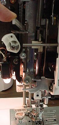
The pressure required to actuate the threader is modest when it is operating normally. The mechanism can be bent by excessive pressure so look for the problem instead of getting a bigger hammer. Remove the light cover and, as usual, clean any lint or threads from the threader. Use the button to set the needle height, and press the nylon arm down lightly to activate the threader. The picture shows the threader partially activated with the front bail half way to supporting the needle. Check for contact between the threader parts and the needle; on my machine, the finger which passes to the right of the needle just touches the needle and deflects it very slightly -- the threader passes precisely through the center of the eye. I assume the slight contact with the needle is deliberate (the end of this finger is angled appropriately); it does require just slightly more force as this contact occurs. A magnifying glass is helpful when examining the threader and how it passes through the needle eye.
The threader mechanism needs a small amount of oil for smooth operation. Use a flattened paper clip, as suggested under "Oiling", to put a small drop of oil on the two points where the left vertical rod for the threader passes through the frame. To find these points, move the threader via the nylon arm as shown in the picture and note the places where the left shaft is supported (behind each of the two silver screws in the picture). I also add a small drop at the base of the right rod since this rod rotates to actuate the threader -- hard to say if this helps since it is metal on plastic. This is the mechanisim inside the cover which actuates the threader; note the fiber washer at the top end of the rod to cushion shock if you let the spring snap the lever back - a little oil or grease on this rod is also a good idea.
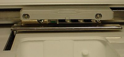
The foot sensor occasionally fails to sense the foot position and asks that the foot be lifted when it is already up.  Cycling the foot up and down generally gets things working properly and the warning window disappears. The picture at right (click it to enlarge) shows the foot sensor mechanism as seen from the back of the machine. As the foot is raised, the item labeled "Lifter" moves the sensor arm up. This activates the switch in the sensor to notify the computer that the arm is in the up position. We don't know why the computer sometimes fails to recognize that the foot is in fact up nor why cycling the foot up and down makes it work again...
The thread cutter automatically severs both top and bottom thread on completion of one color, in preparation for the new thread color. In addition, the cutter can be activated on demand via the "scissor" button.
 The cutter is driven by the motor via the large white cam on the end of the bottom shaft. A solenoid is used to activate the cutter by connecting the cutter mechanism to this cam. To access the cutter, remove the bobbin arm cover after unplugging power. As usual, the most common problems are due to thread and lint clogging the works so clean the area thoroughly -- this will fix most common problems with the cutter.
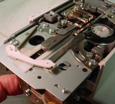
The cutter can be cycled manually to help in finding problems. Press and hold the solenoid's arm toward the front of the machine as shown in the picture, then turn the handwheel ccw slowly and gently -- don't force it if it doesn't turn easily. The solenoid arm can be released as soon as the cutter starts to move and the cutter will complete the cycle as you continue to turn the handwheel; if the solenoid is held closed the cycle will repeat until the solenoid's arm is released. The cutter will slide from left to right and then return; the picture shows it in mid-cycle. The cutter is the flat piece with the large hook toward the right end (under the needle in the picture); the hook pushes the threads out of the way as it moves to the right, then grabs the threads and severs them on the way back (the tiny curved knife is below the right end of the flat spring which covers the hook when retracted). Notice the small stainless steel finger which swivels out to prevent the bobbin from rotating while the thread is cut, also the stainless spring which covers the hook when retracted - this helps hold the thread as the hook pulls it. Lubrication is not needed - the sliding surfaces are metal on plastic for low friction; lubricant would hold dirt and cause trouble (although the cam has a small amount of white grease on it).
The thread cutter generally works well if kept clean. Check for thread and/or lint below as well as on top if you experience failure to reliably sever the threads. If you use adhesive it might get transferred to the cutter via the thread so be alert for that. More details on the cutter blade.
The ULT notices when the bobbin is running low and warns the user with a beep and a window message displayed on the LCD screen. This warning is sometimes erratic and cleaning the sensors involved may improve things. If sufficient lint collects on the sensors then the warning will never appear and you will run out of bobbin thread.
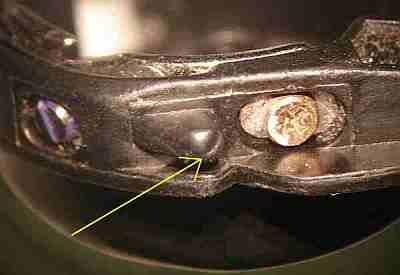
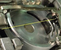 The amount of thread on the bobbin is sensed using a LED (light emitting diode) whose beam shines through the race and the shuttle onto a photo sensor on the other side; the path of the beam is shown by the yellow line in the picture (the LED is visible at the right end of the line). The sensor (which looks similar) is located under the little shelf on the left in the picture and is hard to see except with a mirror. The race is cut away to allow the beam through and the shuttle has an opening on each side of the bobbin such that the beam passes through it adjacent to the center core of the bobbin. Naturally, lint collects on the LED and photo sensor. Crack a Q-tip about 1/2 inch from the end so it forms a right angle and use this to carefully wipe the lint from both the LED and the sensor. It's a good idea to clean these each time you clean the shuttle and race, i.e. often. Also check the holes in the shuttle and clean if needed.
Some users find that the low bobbin alarm occurs when considerable thread remains on the bobbin. There is an adjustment for this which your dealer can make or, if you're brave and mechanically inclined, you can adjust it yourself.
 Thread can accidentally find its way to where it shouldn't be while winding a bobbin. Should this happen, remove the bobbin being wound and as much errant thread as possible by pulling and cutting it away.
Remove the round plastic piece (shown to the right of the opening in the picture) on the bobbin winder shaft if thread has found its way below it -- simply pull up on it . This piece has two tiny blades inside which are retained by a second plastic piece that snaps into the bottom of the first piece; occasionally, the bottom piece will un-snap as it is removed so don't tilt it until it is away from the opening -- the blades can be easily re-inserted if they come out, then the bottom can be pressed in to click the snaps. When re-installing this piece, note the slots in the bottom extension which engage the teeth on the white plastic part at the base of the shaft. Press the piece down until it contacts the white piece, then rotate it while pressing down lightly to engage these teeth. Use a gentle touch so you don't break the plastic.
If there is concern about thread having found its way further into the winder mechanism, remove the cover by loosening the two screws and lifting the cover straight up. The finger on the arm at upper right is activated by thread filling the bobbin and terminates winding by opening the switch at lower left -- work the arm back and forth to see how it operates. The bobbin winder has its own motor, so stray threads in the winder won't cause the handwheel to lock up.
There is no obvious way to adjust this mechanism so it will wind more or less thread onto the bobbin -- if anyone finds an adjustment please write so we can include it. (A rough way to make it wind more thread would be to file the finger down but the plastic might be difficult to work and obtain a smooth result which wouldn't damage the thread.)
The ULT bobbin winder design doesn't work as well as the one on my sewing machine. I think this is because the guide/tensioner is too close to the bobbin being wound, causing the thread to build up in the center of the bobbin -- the guide is much farther away on my sewing machine. I'm looking for an external guide/tensioner, perhaps one that can be mounted on the top of the ULT with double sided tape.
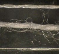 Bobbin thread (as seen through our microscope) seems to differ from regular thread in that it is finer and generally smoother. The top thread in the picture is from a Nebs pre-wound bobbin, the middle thread is "bobbin filler thread" from a local store, and the bottom thread is "invisible nylon thread for overlock (serger) machines" which I purchased at JoAnn's without understanding what it was (it was on sale!).
Winding bobbin filler thread on the ULT results in a bobbin which feels soft when you squeeze it, probably because the large number of protruding fibers prevents it from winding as tightly as the type of thread found on the Nebs. There is relatively little thread on the bobbin compared to a Nebs.
Winding the nylon thread on the ULT is tricky because it is almost invisible. Further, it tends to wind unevenly on my machine so I have to guide the thread onto the bobbin by touching it with my finger. I also tried winding it while holding slight tension with my fingers before the thread went into the guides; this added enough tension that it caused the recycled Nebs bobbin to distort. When the plastic finger which shuts off the bobbin winder contacts the thread being wound it makes an odd noise but doesn't seem to affect the winding detrimentally. Once I figured out how to do it I was able to wind a huge amount of this very fine monofilament thread onto a bobbin and it seems to work very well (and it is cheap). It is a bit of a hassle winding bobbins so I may continue using the white Nebs prewound bobbins (the nylon thread is really cheap ;-). The invisible thread works well so I now use it for most projects although it makes designs a bit stiffer than normal.
If thread tends to bunch at the top or bottom of the bobbin being wound, the height of the guide at the left of the opening can be adjusted by loosening the screw which secures it, then sliding it up or down slightly and retightening. If thread bunches in the middle of the bobbin, guide it up and down slightly with your finger during winding. This is a minor design problem in the ULT; the bobbin winder tensioner is too close to the bobbin.
 The ULT's internal computer determines which hoop is installed by examining the three switches located under the hoop latch handle; these are the little white arms visible in the picture, the first just under the center of the handle, the other two further to the right. With 3 switches, the ULT can sense 8 different situations: 7 hoop sizes plus "no hoop installed".
Examining the hoops supplied with the ULT I noted bumps to activate these switches molded into the part of the hoop which mates with this latch. Each hoop size has a different pattern of bumps.
ULT firmware release 4.0 allowed using the "Borders" function with the 5x7 hoop but this release is no longer available on the Brother site. The 4.01 release precludes using the "Borders" function unless a special hoop is installed. I wanted to experiment with the Borders firmware in my machine but didn't know enough about Borders to justify the (high) cost of this hoop so I added a bump to my 7x5 hoop to try Borders using my 4.01 firmware. Of course, the 7x5 hoop is smaller than the Borders hoop so it may be possible to crash the foot into the frame if I push the limits... It is not possible to easily fake out the 10x6 hoop for borders because it has the middle bump molded in and this must be missing to activate borders.
 To cause the 7x5 hoop to pretend that it is a Border hoop, the switch nearest the center of the handle must be activated. The picture shows my 7x5 hoop with a (temporary, cardboard) bump added to depress the appropriate switch. The positions of the 3 switches are denoted by the blue dots. The exact position/shape of the new activating bump isn't super critical, it just has to depress the little lever on the switch.
This was adequately done with a 1/4" wide piece of cardboard (the type used for cereal boxes). I bent the cardboard at a right angle about 1/8" from the end and then cut it off about 1/4" past this bend. I put this edge-up in the desired position and verified that it looked about like the bump near the left dot. I cut a 1/4" wide strip of duct tape about 2" long and, starting at the tip of the "S" arrow, laid it in the opening to secure the cardboard in place, finishing at "F" (the tape isn't visible in the picture because it is edge-up too). This should result in a hollow bump of approximately the correct shape in approximately the correct spot (my cardboard bump, shown above the right blue dot, is shaped about like the molded bump above the left blue dot). I cut another short piece from the 1/4" cardboard strip, rolled it up, and stuffed it beneath the center of the new bump to make it a little stronger -- so the switch doesn't flatten it out.
When installing the hoop, I squeeze the securing handle so the latch can enter without pressure, insert the hoop, and release the securing handle to lock the hoop in place. To remove the hoop I squeeze the handle and gently slide it out; I don't force it because if it hangs up I don't want to break a $witch. When done experimenting, I remove the tape.
So far, I'm not too impressed with Borders - perhaps I need to read the manual (which wasn't included with this trick :-)
Users occasionally have trouble with the embroidery arm, a common symptom being that the hoop does not center itself when power is applied. Another symptom is the arm not moving as required for the design, distorting the design or making gross errors in outlining. Another symptom is failure to correctly identify the type of hoop installed or sometimes failure to recognize any hoop is installed.
Arm problems are usually caused by a poor connection between the ULT and one of the motors or switches in the arm. One common reason is dirt or thread in the electrical connector located at the front of the arm. Separate the arm from the ULT and use a bright light to examine the gold contacts in the arm and in the machine proper. Use the brush or a vacuum cleaner to remove any foreign material; careful cleaning even if you don't see any dirt sometimes cures the problem. Another common reason the arm mis-behaves is a broken ribbon cable in the arm. The wires between the motors and the connector are a delicate ribbon cable and the ULT seems prone to failures here -- this requires a visit to your dealer for repair. A possibility for failure to recognize the hoop properly is the switches in the arm are stuck or broken.
Less is more when it comes to oiling our ULT. Excess oil attracts lint and small bits of thread which can then build up and cause trouble, plus excess oil can get onto fabric being embroidered. We use clock oil because it doesn't dry up; it is expensive when judged by cost per ounce but an ounce is a lifetime supply for all our sewing machines and clocks (a reasonable alternative is any synthetic motor oil - Mobil 1 or Slick50, etc). To apply oil, we made a tool by hammering the end of a straightened paper clip flat, then filing this flattened part to a point. Dip this into the oil 1/8" or so to pick up a small drop, then touch the point to the place where oil is needed; this applies a controlled amount of oil to the precise spot desired. The oil will pull itself into a joint by capillary action -- wipe away any oil which gets onto adjacent surfaces with a bit of paper towel so it doesn't attract lint. Avoid oiling with a can or squeeze bottle, it is too hard to control the amount applied.
The only points we oil are accessed by removing the light cover (pg 8-1). The needle shaft slides in metal bearings so we oil these support points. There are several rotating joints (with metal bearings) associated with driving the needle and we oil these too; in particular, put a drop of oil on the bronze bearing. There are some joints which are metal on plastic; oiling these is optional since plastic is typically self-lubricating.
While the light cover is open, check carefully for stray threads in this area. Pay particular attention to the bronze bearing on the crank which drives the needle -- thread here can lock the machine completely and is very difficult to extract, generally requiring removal of the needle bar assembly for access to the screw which secures the bearing and the arm which it drives. In the picture you can see the small pin we added in the hole near the bronze bearing -- this helps to keep threads out of the bronze bearing and is easy to do. This pin must be short to avoid hitting nearby parts; a plastic or wood pin should be a press fit with a little Super Glue or Loctite for security. Thread can enter the bronze bearing on the left or right end; the pin protects only the right end so it isn't a complete cure for this common problem.
Thread or lint, when found on a moving part that needs lubrication (like the bronze bearing or the needle bar) should be removed, of course. Thread and lint wick the oil out so this is generally a clue that the bearing needs oil.
We don't oil the gears or cam below the shuttle. It is well known that gears of nylon running against gears of acetal are self lubricating. Our best guess is that the white and black gears are from these two materials, chosen so lubrication won't be needed in this area because the engineers realized the potential for lint and threads here. Opinions could differ on this and we don't have solid facts so take this for what it is worth.
There may be other points which need lubrication -- we rely on the dealer to handle these.
After years of use, the feed dog may fail to come up when sewing mode is selected. Verify that the switch near the embroidery arm connector is moved to the left else the feed dogs can not move up. After moving this switch to the left, turning the hand wheel for about two revolutions should cause a click in the area near the feed dog and they should then move up and down in sync with the forward and back movement.
The feed dogs on my machine stopped moving up and down although they moved forward and back normally. There is a little lever extending down from the sewing arm, just left of the feed dog switch - this will normally move to the left and cause the audible click. If the feed dogs are not moving up and down, put modest pressure to the left on this lever and turn the hand wheel - if this lever moves left within two revolutions than you've run into the same problem I had.
The solution is to unplug the machine, remove the needle plate and carefully remove lint and threads from the white plastic piece below and to the right of the race. It's awkward to get to but tweezers alternating with a Qtip worked for me. Lint absorbs the grease from this area, eventually resulting in increased friction. A dab of white grease on the top of the outer white part and more white grease on the white plastic part it slides on got my machine working normally again. It doesn't take much grease, a little dab'll do ya ;-)
Many gears in the ULT are plastic (shafts, bearings, etc. are metal). Some sales pitches from dealers for other machines suggest that plastic gears are inferior to metal gears and thus are a reason to choose the competing machine over the ULT.
Brother's engineers likely spent considerable time selecting the best material for each part in the ULT. We seldom hear of a broken part in a ULT other than when something jams the works. Most jams just stop the machine without a broken part. In fact, when properly chosen for the application, plastic gears are often superior to metal gears. The main drawback to plastic gears is that the mold needed to produce them is VERY expensive.
Some favorable features of plastic gears are:
Another sales myth is that the ULT's plastic gears will fail due to heat. Heat in the ULT is modest and the most heat sensitive part of the ULT is its computer, not the plastic gears. When you find that heat from the ULT burns your arm, it will be time to worry about the gears :-)
Brother provides a good explanation of how to retrieve (download) their free ULT software update and then install it into the ULT via floppies. Updating the software may add new features or fix existing problems but it does not change the model from 2001 to 2003 (see below for details). Owners are often unfamiliar with what occurs during this process so this section attempts to explain some of the details so you can reason through to figure out how it affects your ULT. None of this is critical to using your ULT but some owners may find it interesting and/or helpful.
The ULT contains a computer which uses several types of memory for its operations. The types of memory and their characteristics are:
Some explanation of the terms used above may be helpful for those who are unfamiliar with microcomputers. ROM is the acronym for Read Only Memory. PROM is Programmable Read Only Memory -- it is not easily erasable (factory written and installed). Flash PROM can be erased while it is installed in the ULT by using special software found in the PROM. EEPROM can be erased and re-written in small pieces by the ULT software based on user input -- when you change the names of the colors this is remembered in EEPROM so it will be there when power is turned off and then restored. RAM (Random Access Memory), unlike all types of ROM, loses its contents when power is turned off so it is only useful for temporary storage.
Occasionally the ULT will not allow a design stored in its memory to be erased in the normal manner. When this happens it is possible to erase ALL designs in memory (including the offending design); move any designs you don't want to lose from memory to floppy before using the following procedure. Turn the machine off, hold down Start/Stop and the Reverse button above it and turn machine on. Hold these buttons depressed until the maintenance screen appears showing buttons 01-40 (this should take about 5 seconds). Release the Start/Stop and Reverse buttons. Select button 19 on the LCD screen to bring up the Memory Clear screen; press OK to clear memory or Close to return to the first screen. Turn power off, wait 10 seconds and turn power back on.
Brother's UK site has the maintenance manual available intermittently, poke around and you may find it; this manual explains how to use all the maintenance buttons on the LCD screen plus a number of adjustments for the adventuresome ULT owner.
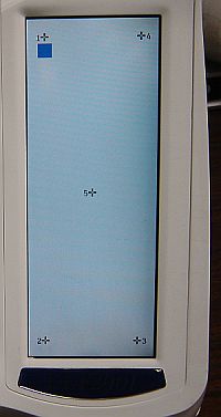 Rarely, the touch screen calibration may drift causing difficulty selecting the desired item with this screen. To re-sync the LCD with the touch screen (per pg 9-3 of user manual), hold the Start/Reverse/Needle buttons depressed and turn power on -- in a few seconds, the screen at right will appear. Release the buttons and use the stylus (on the opposite end of the cleaning brush) to gently touch the center of the cross adjacent to the blue block. Touch the dot at the center of the cross gently, the machine will beep and the block will move to the next cross; touch that cross at the dot and proceed until all 5 points are calibrated, when it should beep once. If you make an error and don't touch precisely, simply go around again. After completing all 5 touches accurately, turn the power off to complete calibration and return to normal operation.
The floppy drive is generally reliable if you are careful to keep lint away from the drive and disks as much as is possible in a sewing environment. If a design won't read into the ULT from a floppy, verify that the design is in PES format and that the size is within the ULT's capability. Then, try a different floppy disk - occasionally a diskette will go bad. Try transferring a different design, preferrably one that you have previously transferred successfully.
When all else fails, a floppy drive may be at fault. It could be the drive in your computer so eliminate that possibility by moving some files to another computer using the diskette which can't be read by the ULT. If this works normally then the ULT floppy may be at fault. Floppy drives can be tested and adjusted but generally it is cheaper and easier to replace the drive.
The floppy drive in the ULT is, from the Brother parts list pdf file: FDDFD-05HG-5661 . This part# is for a TEAC Super Slim Notebook floppy drive. It makes more sense now to replace the floppy drive with an emulator that reads a thumb drive, see the next below.
My floppy drive became unreliable in 2016 so it was replaced with a 1.44mb floppy emulator; this accepts a thumb drive which can be written using the computer's USB. The emulator was purchased on eBay from the vendor floppy_to_usb for $75 (Search eBay for: ULT floppy emulator). Ordered on Friday, it arrived Monday from India - amazing delivery time by DHL.

Installation was straight forward, the most difficult part being removal of the ULT front cover. Once the cover is off and held in position by the upper corner of the machine (as shown in the picture at right) the flat cable can be removed from the floppy by pushing the ends of the retainer for the ZIF (Zero Insertion Force) socket up. The cable is then moved aside to improve access to the 4 screws which hold the metal plate that the floppy mounts to. The floppy can then be removed from the metal plate by removing 4 tiny machine screws.
The emulator has a plastic case and is mounted to the metal plate using the screws supplied; the screws went in hard so I used a little soap on them to make it easier.  I added an arrow on the metal shield to keep track of which direction was UP but the holes in the shield and emulator case only line up one way so it would be difficult to get it mounted wrong. I inserted the cable into the ZIF connector and closed its locking mechanism to secure the cable prior to installing the metal plate to the cover. This seemed easier than working the connector after mounting and it was easy enough to screw the metal plate in place while working around the cable. Then the cover was re-installed. Total time was about an hour.
The emulator can't read files in folders so files are simply written to the root directory of the thumb drive. I use EmBird and to write I select "Write to Floppy" just as as I did before, then change the drive letter from A: to H: (Windows assigns this drive letter when the thumb drive is inserted) and EmBird writes the file to the thumb drive. When the thumb drive is inserted into the ULT the red LED on the emulator illuminates for a few seconds as the files are read from the thumb drive to the emulator's internal memory. This read operation can be re-done by pressing the upper switch on the emulator and waiting for the LED to go out. Once the files are read the thumb drive can be removed and the files remain accessible from the emulator's memory. If the files are modified they can be written to the thumb drive by pressing the lower switch and waiting for the LED to go out.
The bulb which lights the sewing area lasted over 2 years on my machine, more than I would expect because I use the machine a lot and often have it on when not actively embroidering. When the bulb failed, I realized how much I needed it. A trip to Walmart's automotive section yielded two Sylvania bulbs #2825 for $1.75 which seem to fit and work just like the original, so now I have a spare. These are 5w bulbs -- the 3w bulbs were right beside them at Walmart so you'll need to be alert to get the correct bulbs. See page 8-1 for information on removing the upper (light) cover. When installing the bulb, avoid leaving a finger print on it or wash it with rubbing alcohol after installation -- small bulbs sometimes run hot and can fail from dirt on the envelope.
My ULT is noisier than I would like so I use earplugs while embroidering. Much of the noise seems to come from the needle lifting and dropping the Q foot with each stitch. I notice also that the plastic part of my Q foot is wearing away in the contact area. I recently purchased the Q+ foot which provides only slightly quieter operation.
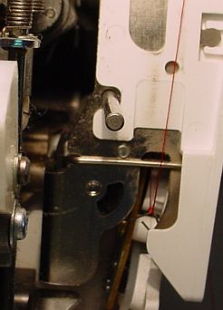 The upper thread sensor requires occasional cleaning to prevent buildup of lint from binding it in one position. Remove the light cover to gain access, the sensor is about 1/2 inch behind the #3 of the upper thread guide numbers. The sensor arm is the hooked wire in the picture with the red thread caught in the hook. The upper thread pulls this sensor arm upwards in normal operation (the foot must be down to activate the upper tension); if the upper thread breaks, this spring loaded arm remains down causing the ULT to alarm shortly thereafter. Lint collects in the little semi-circular hole, just to the left of the hook in the picture - use the brush to remove this lint, then gently pull upwards on the thread to move the arm up and brush some more. The wire sensor arm is visible through the semi-circular hole and will drop to the lower edge of the hole when the arm is released. Gently pulling upward on the thread will move the wire arm so it is at the upper edge of the semi-circular hole.
Outlining is often the last operation in stitching a design. A common problem is that the outline does not accurately meet the stitched areas. Faulty hooping and/or insufficient stabilizer are common causes. When these are not the cause then a third possibility is that the hoop failed to move as commanded.
The hoop is moved by two stepper motors in the embroidery arm; the ULT issues "step" commands to these motors to move the hoop to the next stitch position and counts these commands to keep track of hoop position. The ULT assumes that the hoop moves as commanded and if it doesn't, all following stitches are displaced slightly because of this. These errors add up as the stitching of the design proceeds causing the error between assumed and actual position to increase. If you look very carefully you may see that colors stitched later in a design are shifted slightly from colors stitched earlier as errors accumulate. Since the outline is generally stitched last it shows the maximum accumulated error. The effects are subtle and difficult to tell visually from hooping and stabilizer problems.
Failure(s) to move the hoop often occur because something is interfering with the hoop. For instance: large amounts of fabric are heavy and hard to move, cloth extends beyond the hoop and rubs on something nearby, or cloth falls down the front of the machine, or you accidentally place something nearby so that the hoop bumps into it. Basically, any additional load or friction on the hoop/cloth can cause a failure to move, although the little stepper motors are surprisingly strong.
It is possible to verify that a failure to move error occurred but it takes a little time and effort. When you suspect this problem, at the next color change, change colors and allow it to make only a couple of stitches - enough so you can see where that color starts. Then, remove the hoop and turn off power, wait 10 seconds, and turn power back on. Install the hoop and have it stitch those last couple of stitches again - any difference in position between these and the first set is due to failures to move during prior stitching. Clearly, eliminating the load or friction which causes these stepping failures is the best way to fix this outlining problem. A partial work-around would be to stop between colors occasionally and turn the power off as described above -- each time the ULT powers up it relocates itself by running the arm to the extreme lower right and then goes back to center, thus eliminating any accumulated errors.
Occasionally the machine may lose power or the hoop may unclip while embroidering. This requires re-establishing position so embroidering can continue from where it left off. The following describes how I recover when this happens.
This completes preparation, the next 3 steps accomplish the alignment. Proceed carefully.
This is how I do it, others may find some short cuts but this is the best I've come up with.
A near-empty bobbin sometimes affects tension, causing white heads to appear. This is apparently due to the bobbin jumping around in the shuttle.
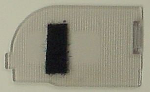 I use Nebs pre-wound bobbins on clear plastic spools. On my machine the un-sided and paper sided bobbins seem to jump around in the shuttle when the thread gets low causing tension and stitching problems. I find I must change these bobbins well before they are empty so the plastic bobbins wind up being more economical. Your machine may be more tolerant but it is something to watch for... Sue Weaver suggested adding a 1/4x3/4" strip of stick-on Velcro loop to the bottom of the plastic window above the bobbin -- this cushion reduces jumping of near-empty bobbins allowing them to be run out completely. I haven't tried the un-sided or paper sided bobbins with this yet but expect it should help them too.
"Nesting" occurs when the thread doesn't form a proper lock stitch and instead multiple threads connect from the design to the bobbin area. This nest is often hard to remove because it is difficult to reach the nested threads with scissors plus it is difficult to clip these threads without damaging the hooped material. When a nest occurs I use a sharp, thin knife and by sliding it between the hoop and the machine I saw through the nest. The most common cause of nesting on my ULT is burrs. If your machine nests and it has been heavily used, check for shuttle wear.
On occasion the knife or scissors used to release a nest damages the embroidered fabric, causing a small hole. To recover, I take a scrap of the same fabric and place it below the damaged area, cover the patch with stabilizer, and Scotch tape it all in place. Then replace the hoop in the machine, back up the stitch point and continue embroidering. Once the hole and a bit of the surrounding area is stitched, stop, remove hoop, remove tape, trim fabric patch, then complete embroidering normally. The back of the work won't be as neat as usual but it saves redoing the entire project.
I use thread directly from cones and have found that cones must be handled carefully to avoid affecting the way the thread feeds off the cone. I use "thread socks"; these are loose knit sleeves fit over the cone to keep the thread from shifting while handling the cone. The thread sock is not removed while using thread and when storing the cone the loose end is simply wound over the sock. I found real thread socks fragile (they stretched and unraveled) so I bought "Glovemates" which are knitted, fingerless glove liners used by surgeons under latex gloves; I cut the end with the finger separators off to make a durable and cheap (17 cent) thread sock. I've found the feed path from the cone to the machine is critical; if the thread snags it is likely to cause a broken needle.
When a needle breaks I try to find all the pieces so I don't have a piece of a needle in the works below the bobbin. Sometimes it isn't possible to find all the parts to a broken needle so there is no choice but to hope it doesn't cause trouble. I occasionally drop a needle into the works while changing needles -- I look for it through the opening, removing the stitch plate if needed. If it isn't visible, I try a magnet inserted through the opening (the type used by mechanics to retrieve dropped bolts). If this doesn't produce the lost needle, I remove the bobbin arm cover and tip the machine which usually produces the needle. I continue the search until I find the dropped needle because operating the machine with a needle floating around loose inside is sure to cause trouble eventually, generally a lockup and possibly a broken part.
I mostly use a small brush when cleaning my machine, occasionally a Q-Tip and very occasionally the vacuum cleaner. I don't blow into my machine or use canned air because it moves the lint around and into hard to reach places.
When I bought my first embroidery machine the previous owner warned me to avoid using sticky sprays; her experience was that they worked well but eventually caused machine problems when the stickum built up on things and attracted threads and lint. Consequently, I have never used techniques which rely on sticky sprays.
I also avoid metallic thread because I have read that it wears parts in the machine plus small particles of metal (chips) dislodge from the thread and work their way into the machine. Perhaps I'm not adventurous enough, but I take no chances with my baby ;-)
While I believe the ULT is a great embroidery machine, with perhaps the best bang for the buck available, it does have some design problems -- mostly solved in earlier machines, the designers resurrected these problems in the ULT. Some have been mentioned previously but the problems we think could be solved by minor changes to the ULT design are collected here for reference.
Inserting the shuttle into the race is more difficult than any other machine I have used. While I don't know how to fix this, I also don't know why it occurred in the first place. Shuttle insertion is a common task when using an embroidery machine and the design shouldn't be released if this can't be accomplished easily.
The bobbin winder doesn't wind evenly. Unfortunately, the tensioner needs to be farther from the bobbin for the thread to wind evenly -- look at older machines and you can see this. The design choice was made in favor of tidy parts arrangement rather than good bobbin winding performance.
The handwheel is prone to having threads enter and wind onto the shaft. My 15 year old Sears doesn't have this problem because the handwheel extends inside the case at constant diameter -- a simple, no cost solution.
A similar problem occurs with the bronze bearing on the crank throw which drives the needle bar -- threads find their way into the opening between this bushing and the crank causing the machine to lock up. A minor change to the way this assembly is machined would shield this opening and avoid one of the major sources of ULT lockups. Existing machines could be made far less likely to lock up by adding a simple (5 cent) plastic part pressed into the hole nearby; we did this and it has worked so far - hard to prove it completely eliminates it because this is an infrequent problem.
The ULT is relatively noisy in operation. Perhaps this is the nature of embroidery machines but it seems like a large part of the ULT's noise comes from the Q+ foot being lifted and dropped at each stitch; a change in the shape of the contact points and/or the plastic used might reduce this noise at modest cost.
When installing or removing a memory card containing designs into the ULT I turn the machine off because this guarantees the card will not be damaged. The card can also be installed or removed if the card icon is visible, see pg 5-1.
A less well defined problem is why the ULT is so sensitive to dirt. I have owned 4 sewing machines, 3 embroidery machines, and a serger; none required the rigorous and frequent cleaning that the ULT demands to avert lock up. Nor have I had any of my other machines lock up.
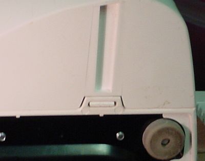
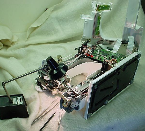
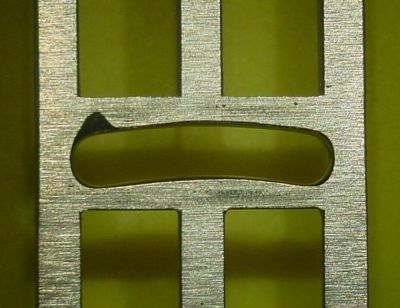
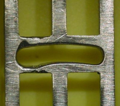
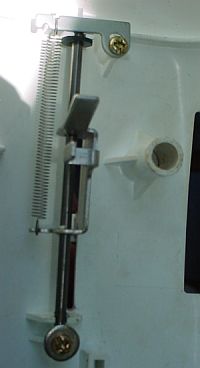
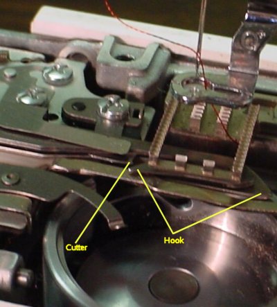